Automation

Automation is set of many technologies like electronics, Electrical, mechanical, Softwares which results automated task or work without any human intervention with great efficiency and reliability. Robotics Process automation, PLC Scada Automation, Industrial Automation , IT automation all are different types of automation.

Artificial intelligence

It is the simulation of human intelligence processes by machines, especially computer systems. Specific applications of AI include expert systems, natural language processing, speech recognition and machine vision.

Mehchanical and Automation

It covers the concepts and processes that are involved in the creation and production of machinery.Person can learn about the theories, mechanics, and materials needed for the manufacturing of a machine.It enhances the understanding of control systems, information technology, machinery structures aelectronics, thermal science, programming, and electrical machinery.

Automation and Industrial Electronics

which is based on learning by acquiring competences and applied by giving great importance to active activities, especially when developing integrated team projects and work placements which represent significant learning opportunities and the the training necessary for the application of electronic and microelectronic devices to the automation of production processes, working with microprocessors, electronic instruments, automatons and robots, etc.

Automation and Robotics

It deals with the design and creation of robots. They use computers to manipulate and process robotic actions. These robots are then used in: -Industries to speed up the manufacturing process. -The field of nuclear science. -Servicing and transmission of electric signals -Designing of bio-medical equipment, sea-exploration, among others.

Tuesday 29 January 2013

Precision Gears

Majority of this types of gears are used where quality matters the most along with durability.
The gear tooth profile of precision gears are grounded after hardening to gain maximum contact with the mating gear and avoid backlash to the maximum.


This ground gears are adaptable to very high RPM with minimum niose.The load carying capacity of precision gears is also remarkable.
These gears are used by Cement Plants, Sugar Mills, Sponge Iron Plants, Fertilizer Plants, Thermal Power Station, Mineral Plants, Chemical Plants, Paper Mills, Mining Industry, Steel Rolling Plants, Textile Plants, Material Handing Equipments, Machine Tools etc.

Industrial Gears

Mechanical Gears


People often looked for constant technological advancement to gauge the progression of a piece of equipment. One noteworthy evolution in the last 50 years is of mechanical drive. Trenchers used to put stuffs in the ground gradually shifted over the last several years to mechanical drive. Mechanical drives used gearboxes, shafts, pulleys, chains and sprockets to drive the trencher chain. Mechanical gear are used to provide a variable output speed from a constant speed power source or to provide torque increase for a variable speed power source as in an automobile. Mechanical drives are less costly than competing electrical drives and their control is much simpler. The disadvantage of these drives is that they are not durable and cannot be controlled as precisely as electrical drives. They cannot transmit as much power as electrical drives when variable speed is essential. They are used in industries ranging from aerospace to mining and heavy industry. With the advanced technology, the working of mechanical drive has become more efficient. Specific characteristics like low-stress, universal mounting, high-strength monobloc casings, high-energy efficiency and low noise level are designed. The monobloc design has increased center distances between the output shaft bearings, making the unit able to withstand significantly higher radial loading. Mechanical drives have internal spaces that have void spaces where residues can be deposited.


Idler Gears 


Idler gear wheel placed between two other gears to transmit motion from one to the other. It does not alter the speed of the output, but it does alter the direction it turns. It is used to ensure that the rotation of two gears is the same. An idler gear is placed between two gears. The idler gear rotates in the opposite direction as the driver gear and the follower gear rotates in the opposite direction of the idler, the same direction of the driver. It is also used to change the spacing between the input and output axes. It does not change the gear ratio between the input and output gears. All the gears and wheels that turn inside the treads of a battle tank are all idler gears that transfer power from the input gear to the output gear to move the tread and move the tank forward. The power take off mechanism includes a gear train with an input idler gear, a first intermediate idler gear, a second intermediate idler gear and an output gear. The input idler gear receives a rotary input and the first intermediate idler gear meshes with the input gear and the second intermediate idler gear. The output gears transmit rotary power to one of the first and second axles.

Worm Gears


Industrial Gears

We service a wide spectrum of industrial gears including mining, pulp and paper, tunnel boring, compressor drives, steel, automotive, aerospace and many more by providing quality gears. We can provide ground gears up to 95" in diameter and cut gears over 20 feet in diameter. Our diverse capabilities include:

External gears to 240 inches diameter.
Internal gears to 270 inches diameter.
Carburized and external and internal ground gears to AGMA Quality 14.
Spur, helical, and double helical gears.
Bevel Gears.
Ground worms and worm gears.
Large machine shop, including extensive CNC capabilities.


Reduction Gears


We are manufacturers and exporters of worm reduction gear box. Casings are made from fine graded cast iron. Worm are made from nickel alloy steel, case hardened and precision ground surfaces. Worm Wheels rims made from Aluminium, Bronze and Phosphorous Bronze (PB2C) casted on Graded Cast Iron hubs. The worm gears are hobbed with multi start hobs to ensure a high load carrying capacity. All these internals are supported on high quality Ball / Roller Bearings designed for life under Grease / oil splash lubrication. Hardened and ground worm drives are available.

Spur Gears


The company manufactures durable and highly efficient spur gears upto 5000 mm OD 50 Module in Cast Iron & Steel (Single, Double & Multi Starts) for Cranes, Material Handling Equipment, For Cement plants, Sugar plants, Chemical plants and Mineral Processing Plants, Coal Handling Equipment, Steel Rolling Mills & Petrochem sectors. They connect parallel shafts, have involute teeth that are parallel to the shaft and can have internal or external teeth. They cause no external thrust between gears. They are inexpensive to manufacture. They give lower but satisfactory performance. They are used when shaft rotates in the same plane. The main features of spur gears are dedendum, addendum, flank and fillet. Dedendum cylinder is a root from where teeth extend, it extends to the tip called the addendum circle. Flank or the face contacts the meshing gear, the most useful feature if the spur gears. The fillet in the root region is kinetically irrelevant.

Planetary Gears


A gearset in which all of the gears are in one plane, grouped around each other like the planets around the sun. The central gear is called the "sun gear". In mesh with it is a circular grouping of gears, called "planet gears", mounted on a rotating carrier. The planet gears also engage teeth on the inner periphery of the "ring gear". By holding any one of the three gear elements motionless, different ratios can be produced between the other two. Planetary gearsets are common in automatic transmissions.

Automotive Gears


Automotive Gears play an important role in trucks, car, buses, motor bikes and even geared cycles. These gears control speed and include gears like ring and pinion, spiral gear, hypoid gear, hydraulic gears, reduction gearbox. Automotive gear ratio is the number of turns of the drive wheels in relation to the number of turns of the engine. If the engine is considered the input and the drive wheel is considered to be the output then the input gear or the pinion is said to mate with the output gear or the ring gear to drive or rotate it. Depending on the size of the vehicle, the size of the gears also varies. There are low gears covering a shorter distance and are useful when speed is low. There are high gears also with larger number of teeth. These high gears cover a longer distance with one revolution of pedal.

Angular bevel gears: Used in rotor craft drive system to redirect the shaft from horizontal gas turbine engine to the vertical rotor.


Bevel gears: Important components on all rotorcraft drive system.


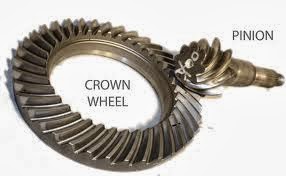
Crown wheel and pinion: Used in motorcycle automotive gearboxes.


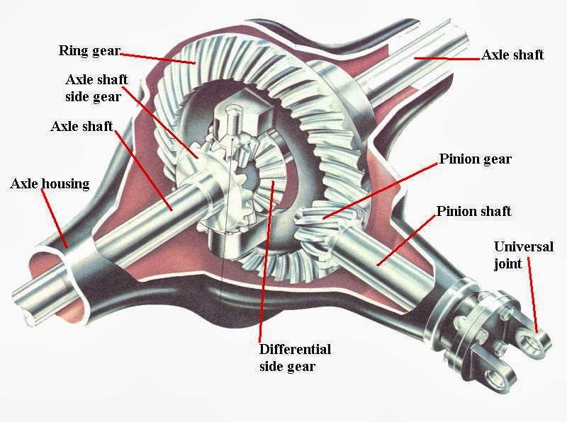
Differential gear: Helps two wheels of the car to rotate differentially with respect to each other.


Fine pitch gear: It is an anti-backlash gear used to minimize errors introduced by backlash.

Helical bevel gears: Used as storage and retrieval units in automobiles.


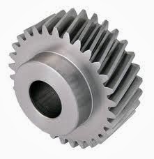
Helical gears: In helical gear the teeth are cut an angel, allowing for more gradual and smoother meshing between gear wheels.

Herringbone gears: Used for power transmission in automobiles. 


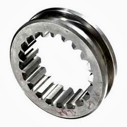
Internal gears: Used in rollers and as tools for creating solid models of drive systems. 


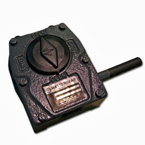
Master gear: Used to determine the accuracy of work gears. 


Ring gears and pinion: Used in heavy truck differentials. Also used to convert the driving force from the drive shaft (power unit) to the drive wheels.


Drive Gears :-
Everyone has seen a bicycle or used one and noticed that it is driven by a large driver gear wheel with pedals attached. Smaller gears at the back are driven round, in turn driving round the back wheel. As the back wheel turns the bicycle moves forwards. Gears driven by chains are used in machinery, motorcycles, in car engines and have many more applications. A chain is made up of a series of links with the links held together with steel pins. This arrange makes a chain a strong, long lasting way of transmitting rotary motion from one gear wheel to another.


Bevel Gears :- 
Bevel Gears connect intersecting axes and come in several types. The pitch surface of bevel gears is a cone. They are useful when the direction of a shaft's rotation needs to be changed. Using gears of differing numbers of teeth can change the speed of rotation. They are usually mounted on shafts that are 90 degrees apart, but can be designed to work at other angles as well. These gears permit minor adjustment during assembly and allow for some displacement due to deflection under operating loads without concentrating the load on the end of the tooth. For reliable performance, Gears must be pinned to shaft with a dowel or taper pin.

(straight tooth bevel gear)

Types:
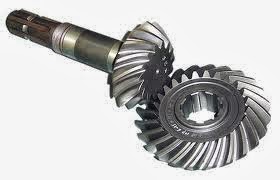
The teeth on bevel gears can be straight tooth , spiral or bevel. In straight tooth bevel gears teeth have no helix angles. They either have equal size gears with 90 degrees shaft angle or a shaft angle other than 90 degrees. Straight bevel angle can also be with one gear flat with a pitch angle of 90 degrees. In straight when each tooth engages it impacts the corresponding tooth and simply curving the gear teeth can solve the problem. Spiral bevel gears have spiral angles, which gives performance improvements. The contact between the teeth starts at one end of the gear and then spreads across the whole tooth. In both the bevel types of gears the shaft must be perpendicular to each other and must be in the same plane. The hypoid bevel gears can engage with the axes in different planes. This is used in many car differentials. The ring gear of the differential and the input pinion gear are both hypoid. They also have sliding action along the teeth, potentially reducing efficiency.

                                                       (sprial bevel gear)

Applications:


A good example of bevel gears is seen as the main mechanism for a hand drill. The bevel gears find its application in locomotives, marine applications, automobiles, printing presses, cooling towers, power plants, steel plants, defence and also in railway track inspection machine.

Straight tooth Gears:-

Straight bevel gears are the simplest of the bevel gears. They are manufactured on precision generating machines by indexing method ensuring that the teeth should be of tapered depth and thickness. Teeth are cut on the outside of the cone. They have a straight tooth geometry, which if extends, passes through the intersection of their axes. Straight bevel angle can also be with one gear flat with a pitch angle of 90 degrees. These have conical pith surfaces that operate on intersecting axes. They can be designed and cut to operate on any shaft angle. In straight bevel gears when each tooth engages it impacts the corresponding tooth and simply curving the gear teeth can solve the problem. Straight bevel gears come in two variations depending on the fabrication equipment. They are grouped into gleason type and the standard type. Major percentage of them is of gleas on type with a coniflex form that gives almost an imperceptible convex appearance to the tooth surface. In the standard form, the gear has no profile shifted tooth. These gears are recommended at less speed and when loads are light. At higher speed they make noise. The most preeminent function of these gears is in a bevel gear differential. Straight tooth gears are also used in chemical industries, steel plant, machine tools, cement plant, textile processing, material handling system, sugar mills and cooling towers etc.

Transmission Gear :-
We are the exporters of automotive engine gears like transmission gears, differential gears, propeller shaft components for trucks, tractors, passenger cars, construction machinery and other LCVs.


Monday 28 January 2013

10 reasons why Mechanical Engineering is the best


There has always been a debate and discussion among all engineering students about which engineering course is the best? Students always love discussing about the best branch of engineering. Though this is a proven fact and it needs no discussion that mechanical engineering is the best still I will be providing 10 reasons over here which make mechanical engineering The Best among all other branches of engineering.

10 reasons why Mechanical Engineering is the best

1) Evergreen Field: Mechanical engineering is an evergreen field. Applications of mechanical engineering have spread over such a wide spectrum that it has penetrated into almost every industry. Mechanical engineering got its application started right from the birth of this universe and it will continue till the end of this universe.

2) Mother Of All Engineering Disciplines: Yeah it’s mother of all engineering disciplines and you know it! Mechanical engineering links all engineering disciplines together and provides a base for all engineering education.

3) Everything Is Mechanical: Mechanical engineering has its application in all fields of life. May it be medicine, construction, automobile or even software and IT industry. Everything you see around you involves mechanical engineering to some extent.

4) Everlasting Scope: Scope of mechanical engineering is everlasting. Mechanical engineering graduates can find career placements in almost every sector, right from construction sector to steel industry and from automobile to software.

5) Best Job Offers: Mechanical engineers get best job offers after graduation. It’s one of the highest paid jobs all over the world.

6) Social Status: Mechanical engineers are respected in every society. They possess a respectful social status among masses. They are like global ambassadors. Wherever they go, they are treated with respect.

7) Most Interesting: Mechanical engineering involves study of some of the most interesting phenomena of science and engineering. The basic focus during study is on subjects such as thermal engineering, fluid sciences, machine design, industrial engineering and production engineering.

8) Even GOD Loves ME: Ever thought GOD also implemented mechanical engineering in nature? Motion of your body, arms, hands and feet involves mechanical engineering. Your heart pumps blood and it runs through all your veins. This is again application of mechanical engineering. The more you look into nature with the eye of a mechanical engineer, you will find more application of it.

9) Best Lifestyle: Do you need a best lifestyle to live in? Mechanical engineering offers you one of the best lifestyles. It’s like a dream come true.

10) Vast Industry: Mechanical engineering industry is vast. Every industry needs mechanical engineers to run its business smoothly.

Do you have more reasons to say? Don’t forget to comment. Let us see how many reasons we can gather here in comments. I hope you enjoyed reading 10 reasons why mechanical engineering is the best course. No doubt It's best engineering course and best engineering branch!

Mechanical Engineering vs. Electrical Engineering

These two branches of engineering are so famous and high in demand that every engineering student wants to know that which among these two is better? Both of these branches of engineering are high in merit in all universities all over the world. It’s really hard to choose one which is better among these two disciplines. I interviewed almost fifteen mechanical and electrical engineers before writing about this issue. Those who were mechanical engineers, they said mechanical engineering is better while those who are electrical engineers, they said that electrical engineering is better. 

So Mechanical engineering vs Electrical engineering – the debate goes on.

Here I would like to present a more logical difference between these two disciplines of engineering and I hope it will help all young students and prospective students to get to know about these two branches of engineering. Because in the end, I personally think it’s someone’s interest which makes him/her choose between mechanical or electrical engineering.


Actually ME and EE are near polar opposites in the engineering world. ME is based on the mechanics field of physics, while EE is based on the electricity and magnetism field of physics.
I have made things quite simple here. If you love solving problems in Mechanics portion of physics then definitely mechanical engineering is for you and if you feel attraction in solving problems in electricity and magnetism then electrical engineering can be a right choice for you. Mechanical Engineering takes you towards things involving machines, mechanisms, physics (forces etc.), manufacturing and production, liquids, gases and more tangible things. While on the other hand, Electrical Engineering takes you towards things involving power, cabling, fuses, electrical appliances production, circuits, semiconductors and generally electricity and energy management and application in a larger scale.
Let us be more practical and look deep into future. Being a mechanical engineer you will learn to build car’s body and engine while being an electrical engineer you will be able to handle/build/manage the car's battery.

Above discussion was dealing with the debate of Mechanical engineering vs Electrical engineering on educational basis and basic differences in their structure. Talking about career opportunities, jobs and pay differences, I will keep things straight for you. In this modern world, you will never be paid higher or lower based on your qualifications. Believe me it’s so true in this world these days. You are paid based on your technical knowledge and experience which you get. So don’t worry about job and pay at this stage. Just choose that branch of engineering which you find interesting. It will help you to do more and learn more within circle of your interest.

I hope this article will help you solve this historical engineering puzzle of Mechanical engineering vs Electrical engineering. Now decision is all yours. Choose wisely because this will be a life time decision for you. You are going to define your future so define it wisely. Don’t forget to leave your comments if you need any help and to learn more.

Types of mechanical engineering


Many students keep asking us about different types of mechanical engineering. They are not clear about different areas of mechanical engineering. Actually this question is a bit confusing in itself. We call it“sub disciplines” instead of “types”. So “Types of mechanical engineering” actually are “sub disciplines of mechanical engineering” in a true sense. All different types of mechanical engineering have something in common which is study and application of heat and motion. Here are some of the well known types of mechanical engineering (or sub disciplines in other words):
Manufacturing engineering:  Manufacturing engineering is a type of mechanical engineering which deals with study and analysis of different manufacturing practices. It deals with research and development of machines, machine tools, parts, products, equipment, processes and systems etc.
Thermal engineering: As the name suggests thermal engineering deal with cooling and heating of processes, closed environments or equipment etc. Mechanical engineers in this area of specialization are taught to keep any system at optimum temperature.
Automotive or Automobile engineering:  Automotive engineers design, build, maintain, and operate self - propelled vehicles for use on land or sea, in air or space. From manufacturing of car parts to assembly of car parts, all is covered under umbrella of automobile engineering. This is one of the most interesting and most demanding types of mechanical engineering.
Acoustical engineering:  Acoustical engineers manipulate and control vibrations and they work on reducing unwanted sounds in any system or process.
Aerospace engineering: In this branch of mechanical engineering, students are taught things like design, construction, operation and support of aircrafts, spacecrafts and other air vehicles. They are responsible for the research, design and production of spacecraft, aircraft, aerospace equipment, missiles and satellites.
Naval Engineering:  This is one of the types of mechanical engineering which deals with marine structures. Naval engineers are responsible for design, analysis, maintenance and manufacturing of marine vehicles and other related structures.
Biomedical engineering: Biomedical engineers study both the fundamentals of mechanical engineering and human anatomy and physiology.  They design and develop biomedical products and products which help people with different injuries like spinal injuries etc. This is one of the best types of mechanical engineering which is serving medical field in a very positive way. Many human disabilities can now be recovered due to the efforts of biomedical engineers.
Structural analysis: This is a branch of mechanical engineering as well as civil engineering. Students in this branch try to learn how and why structures fail and what possible measures are to e taken to save any structure from failing.
I hope after reading this article, you will be able to understand all basic types of mechanical engineering. These sub disciplines as mentioned above are very fundamental and basic areas of specialization for mechanical engineers. All these fields include study of basic mechanical engineering concepts and then at later stage students are encouraged to opt for their areas of interest.

Air Brake (road vehicle)


Air brakes or more formally a compressed air brake system is a type of friction brake for vehicles in which compressed air pressing on a piston is used to apply the pressure to the brake pad needed to stop the vehicle. Air brakes are used in large heavy vehicles, particularly those having multiple trailers which must be linked into the brake system, suchas trucks, buses, trailers, and semi-trailers in addition to their use in railroad trains.

Supply system:-
The air compressor is driven by the engine either by crankshaft pulley via a belt or directly from the engine timing gears. It is lubricated and cooled by the engine lubrication and cooling systems. Compressed air is first routed through a cooling coil and into an air dryer which removes moisture and oil impurities and also may include a pressure regulator, safety valve and a smaller purge reservoir.
Advantages:-
Air brakes are used as an alternative to hydraulic brakes which are used on lighter vehicles such as automobiles.Air brakes have several advantages for large multitrailer vehicles:
1). The supply of air is unlimited, so thebrake system can never run out of its operating fluid, as hydraulic brakes can. Minor leaks do not result in brake failures.
2). Air line couplings are easier to attach and detach than hydraulic lines; there is no danger of letting airinto the hydraulic fluid. So air brake circuits of trailers can be attached and removed easily by operators with no training.
3).Air not only serves as a fluid for transmission of force, but also stores potential energy. So it can serve to control the force applied.
4).Air brake systems include an air tank that stores sufficient energy to stop the vehicle if the compressor fails.
5).Air brakes are effective even with considerable leakage, so an air brake system can be designed with sufficient "fail-safe" capacity to stop the vehicle safely even when leaking.

Honda develops new technology to weld steel and aluminum together


Although some engineers have had success in spot welding steel and aluminum together, it has largely been considered impossible to achieve reliable, continuous welds directly between the two dissimilar metals. 

A diagram illustrating Honda's variation on Friction Stir Welding


That changed last Thursday, however, when Honda Motor Company announced that it has devised a technique for doing that very thing. The results, which include lower vehicle weight and better performance, can be seen in the 2013 Accord.

The Honda team developed a variation on Friction Stir Welding, in which metals are joined via mechanical pressure – it's the same technique that has been used for experimental steel/aluminum spot welds in the past. As Honda explains it, “This technology generates a new and stable metallic bonding between steel and aluminum by moving a rotating tool on the top of the aluminum which is lapped over the steel with high pressure.” The welds that result are reportedly as strong or stronger than those made using regular Metal Inert Gas welding.
Steel/aluminum subframes built with the new technique are said to be 25 percent lighter than those made entirely out of steel, which should translate into improved fuel economy. The process also made it possible to alter the structure of the subframe, so that the mounting point for the suspension could be relocated – this change has reportedly increased the rigidity of the mounting point by 20 percent, and thereby improved the car’s dynamic performance.
Additionally, the new process uses about half the amount of electricity as Metal Inert Gas welding, and the machinery it requires isn’t as large as that traditionally used for Friction Stir Welding – in fact, it can be attached to an industrial robot. The technique can also be used for aluminum-to-aluminum welding, without any hardware changes.
A new non-destructive inspection system, incorporating an infra-red camera and a laser, is used to check all of the steel/aluminum welds.
                                               
Source: Honda