Thursday 24 October 2013
PPT ON DTS-i
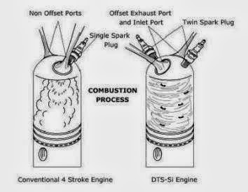
As it is for spark ignition so it will be applicable for only petrol engines. This technology is used for the efficient combustion of the charge (i.e air-fuel mixture). In it we use " two spark plugs" so that the fuel is ignited properly, for maximum economy and efficiency.
Digital - Since the spark generation will be initiated by a microchip.
Twin - Since two spark plugs will be used.
Spark ignition - Since the ignition will be done via a spark.
Monday 14 October 2013
What is Turbo-Charger ?
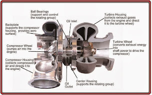
A turbocharger, or turbo (colloquialism), from the Latin "turbō, turbin-" ("a spinning thing") is a forced induction device used to allow more power to be produced by an engine of a given size. It consists of a turbine wheel and a turbine housing, converts the engine exhaust gas into mechanical energy to drive the compressor.
The gas, which is restricted by the turbine's flow cross-sectional area, results in a pressure and temperature drop between the inlet and outlet. This pressure drop is converted by the turbine into kinetic energy to drive the turbine wheel.
There are two main turbine types: axial and radial flow. In the axial-flow type, flow through the wheel is only in the axial direction. In radial-flow turbines, gas inflow is centripetal, i.e. in a radial direction from the outside in, and gas outflow in an axial direction.
Up to a wheel diameter of about 160 mm, only radial-flow turbines are used. This corresponds to an engine power of approximately 1000 kW per turbocharger. From 300 mm onwards, only axial-flow turbines are used. Between these two values, both variants are possible.
As the radial-flow turbine is the most popular type for automotive applications, the following description is limited to the design and function of this turbine type.
In the volute of such radial or centripetal turbines, exhaust gas pressure is converted into kinetic energy and the exhaust gas at the wheel circumference is directed at constant velocity to the turbine wheel. Energy transfer from kinetic energy into shaft power takes place in the turbine wheel, which is designed so that nearly all the kinetic energy is converted by the time the gas reaches the wheel outlet.
Sunday 13 October 2013
WHAT ARE THE SCOPES, CAREER PROSPECTS, DEMANDS AND PAY SCALES OF MECHANICAL ENGINEERING IN COMING YEAR ?
Mechanical Engineering finds application in all fields of technology. It is one of the primitive branches of Engineering which have remained always in demand and continue to be in the future. This is why Mechanical trade is called as an Evergreen trade (branch).Mechanical engineering is one of the oldest branches of engineering. It is also referred to as the ‘mother’ branch of engineering. Another appealing feature of mechanical engineering is that the application base of this field of study is extremely broad and diverse. Almost all inventions during the ancient period and a vast majority in the modern era are direct contributions of one or the other application of mechanics. Mechanical engineers have always been needed as an essential staff personnel in various industries of both public and private sector. Their work criteria changes according to the type and domain of the company they are working with.As the Industrial sector has drastically risen in pace, the need for more mechanical engineers has increased exponentially. Every manufacturing and production industry needs mechanical engineers to carry out jobs efficiently and flawlessly for their companies.
The aforementioned are the conventional roles and responsibilities of mechanical engineers. However, times have changed. Nowadays the scope of mechanical engineering is expanding beyond its traditional boundaries. Mechanical engineers are focussing their attention towards new areas of research such as nanotechnology, development of composite materials, biomedical applications, environmental conservation, etc.
Start Early :-
To make mechanical engineering your chosen career path, you must have affinity for the way different machines function. This trait can be observed from early childhood when children try to tinker around with different machinery in their immediate vicinity. Such kids often tend to take apart mechanical toys, clocks, bicycles and then they try to assemble them back again.
These children are so innovative that they may even try to make new things. Here, parents have a special role to play. They must understand that the child possesses an inquisitive mind that is interested in gaining knowledge about machinery and not in breaking or destroying things. Parents must encourage the child’s curiosity to know more about different gadgets and machines in and around the house.
During schooling, the quest to play around with machinery increases all the more. This curiosity often culminates with the child opting for science with the PCM subject combination.
Is it the Right Career for Me?
Like other career paths, the entry into this particular branch of engineering also requires you to possess certain basic traits. First and foremost, you must have a penchant for mechanical components and machinery and how these machines work. Then you must be good at physics, chemistry and mathematics. You must also have skills such as an analytical bent of mind, logical reasoning and problem solving.
Further, you must have immense patience, physical strength, ability to work for long hours and an inventive spirit that are essential ingredients for becoming a successful mechanical engineer.
What would it Cost Me?
A graduate programme from a private engineering institution will cost you anywhere between Rs. 1,0,000 to Rs. 3,00,000 annually. However, in a reputed government run establishment such as the Indian institute of Technology (IIT) or any regional engineering college, you will have to pay an annual fees in the range of anywhere between Rs 30,000 to Rs 40,000.
Funding/Scholarship
Educational institutes offering programmes in mechanical engineering generally extend scholarships to students from socially and economically backward classes. For example, IITs waive off the complete tuition fees for students belonging to the socially backward communities. Scholarships, freeships, stipends and financial assistance are also provided to students on the basis of merit and other qualifying criteria.
Step-by-Step:-
Passing 10+2 with PCM (Physics, Chemistry and Mathematics) is the first step you take towards becoming a professional mechanical engineer. To be eligible for a graduate programme (BE/BTech) in a college, you should have scored at least 50% marks and 60% for being eligible for IITs (Indian Institute of Technology) in 10+2 with PCM as subjects. After this, you can sit for various entrance examinations such as:
• The Joint Entrance Examination for IITs (IITJEE) for admission to various IITs
• All-India Engineering Entrance Exam (AIEEE) for admission to various National Institutes of Technology or regional engineering colleges
Apart from these, there are hundreds of engineering colleges across the length and breadth of the country where you can get into a graduate programme in mechanical engineering. Some of these colleges conduct their own entrance exams whereas some accept AIEEE scores.
You can also opt for a diploma in engineering from a polytechnic. For obtaining a diploma, the basic eligibility is completion of Class 10 with 50% marks. The duration of these diploma courses is three-years for regular and four-years for part-time study.
You can also go for an associate membership qualification from the Institute of Mechanical Engineers, which is considered at par with the diploma earned from a state run polytechnic or a university degree. Another option is to earn a similar qualification offered by the Institution of Engineering (India). Diploma holders can also get direct entry into the second year of a graduate program (lateral entry).
Subjects in Mechanical Engineering:-
Mechanical Engineers have to study a lot of physics, Engineering drawing, machine drawing and many more concepts such as :-
1). Thermodynamics
2). Strength of Materials
3). Electrical Circuits
4). Statics
5). Dynamics
6). Kinematics
7). Materials Science
8). Theory of Machines
9). Fluid Mechanics
10). Heat Transfer
11). Manufacturing
12). Machine Design
13). Laboratory Methods
14). Vibrations
15). Engineering Economics
16). Metallurgy
17). Manufacturing Process.
18). Computer Aided Design/ Drafting (CAD)
19). Automobile Engineering
20). Industrial Automation and
21). Robotics
After successful completion of the graduate program, you can go for the two-year masters program in mechanical engineering or ME/MTech. If you are interested in pursuing a post-graduate programme in mechanical engineering from any of the IITs, then you must appear for the Graduate Aptitude Test for Engineers (GATE).
These days many engineering colleges are offering a dual (BE/BTech and ME/MTech) programmes. Some other institutions are offering a combination of an engineering degree along with a management programme.
In case you are interested in further studies, you can go do a PhD or even opt for a management degree from a reputed business school.
Job Prospect
Since mechanical engineering is the broadest of all engineering fields, the job prospects on offer for skilled mechanical engineers are aplenty and unending. Mechanical engineers are required to design, test, manufacture, install, operate and maintain a wide array of machines and mechanical systems that are used in countless industries. These professionals can find employment both in the government and private sector undertakings.
Major industries that employ mechanical engineers include automobiles, space research, aeronautical, energy and utilities, air conditioning, bio-mechanical industry. Other major employers include giant manufacturing plants, air conditioning and refrigeration industry, turbine manufacturing plants, oil and gas exploration and refining industries and the agricultural sector.
In the government sector, mechanical engineers can provide their knowledge to various government run projects in the role of technical experts and consultants. They can also work in private engineering companies that provide technical consultancy to both government and corporate firms.
These engineers can also hold high managerial positions in government as well as private sector organisations according to their field of expertise and educational qualifications.
Pay Packet
Mechanical engineering offers a wide variety of career opportunities to job aspirants. The average monthly salary of mechanical engineers who are new to this profession is approximately in the range between Rs.15,000 and Rs.35,000. Good campus placements can fetch even better packages for deserving students. Mechanical engineers who hold a post-graduate degree from a reputed academic institute tend to get better offers than diploma and degree holders.
From here on the annual pay packet depends on a number of factors such as the skill set possessed, experience, expertise, the employer, nature of roles and responsibilities, etc. Highly skilled mechanical engineers can easily command pay packets as high as Rs 40-45 lacs per annum.
Demand and Supply
There is great demand for skilled mechanical engineers in different segments of the industry. Their expertise is required in traditional manufacturing industries such as automobiles, aviation, shipping, aerospace, power plants and machinery manufacturing. In recent times, the services of expert mechanical engineers have even been sought in fields such as nanotechnology, biomedical engineering, energy conservation and environmental engineering.
There is also great requirement for mechanical engineer consultants who have management skills along with technical proficiency. The primary role of such professionals is to manage both technology and people and firms that provide engineering consultancy require them.
Various engineering colleges and polytechnics across the country are doing their best to meet the burgeoning demand of skilled mechanical engineering professionals.
Market Watch
The job market for mechanical engineers is perennial. Even the vagaries of the global economic crisis could not knock out the demand for these professionals in the Indian job market. Although some branches of mechanical engineering went out of focus during the meltdown period, the overall situation was much better as compared with other careers. On the brighter side, things are getting back to normal and this evergreen career path is again gaining coin amongst career aspirants as it did during the pre-meltdown years.
In fact, this is a period of resurgence for mechanical engineers. They not only have countless options in the industrial sector but they can also make foray into new realms of technology and even get into management and technical consultancy.
According to a survey, mechanical engineering is amongst the most sought after branches of engineering preferred by students seeking admission to various technical institutes across India in the recent years.
International Focus
Highly qualified professionals from this field, such as post-graduates from various IITs, often seek suitable employment in foreign countries. It is not that only highly qualified mechanical engineers get opportunity to work abroad. If you are employed in a multinational company, you may also get the chance to work on offshore projects
Positives/Negatives
+ives :-
• There are umpteen job openings and you will not remain unemployed
• Constant involvement in the development of new components, gadgets and machines
• Innovative contribution to the new frontiers of science such as nanotechnology, biomedical engineering and environmental sciences
• Not hit by recession or global economic meltdown
-ives :-
• Working conditions can be adverse at times
• Deadlines and work pressure can exact a heavy toll on the body and mind
• Physically strenuous and not for the weak
Different Roles, Different Names
Mechanical engineering is considered the ‘mother’ of all branches of engineering. In this context the roles and responsibilities held by a mechanical engineer are different and depend on their area of specialisation and the industry they are working for.
In broad terms, the job profile of mechanical engineers can be classified into the following functional segments:
• Research and Development (R&D): Engineers whose role is to do research and then plan for new machines and their constituent parts.
• Design: Professionals whose responsibility is to draft technical drawings, manually or with the aid of computers.
• Production: Engineers who supervise the manufacturing of mechanical components and machines.
• Analysis and testing: Engineers who analyse and test different types of machines and their parts to ensure that they function flawlessly.
• Installation: Professionals who install machines and mechanical parts at the client location.
• Maintenance: Engineers whose primary role is to ensure that machinery is working as per specifications.
Top Companies
1. Automobile and auto part manufacturers
2. Aerospace industry
3. Various Government sector undertakings
4. Aviation companies
5. Steel plants
6. Thermal plants and gas turbine manufacturers
7. Air conditioning and refrigeration industry
8. Shipping industry
9. Engineering consultancies
10. Armed forces
Tips for Getting Hired
1. It is advisable to earn a post-graduate degree in this field
2. Computer proficiency is a must these days
3. You must have excellent communication and interpersonal skills
4. A management degree further brightens your career prospects
What is Digital Twin Spark Ignition (DTS-i) ?
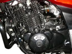
DTS-i - Digital twin Spark Ignition is a revolution in the modern motorcycling era in the country today and we are the first to offer it to Consumers. This technology offers phenomenal performance augmentation and was introduced for the first time on the highly successful Pulsar twins. It is also being patented by Bajaj Auto Ltd.For faster and better combustion. Currently one spark plug at one end of the combustion chamber is the conventional practice. The flame front created by the spark takes some time to reach the farthest portion of the combustion chamber. This leads to slower burning of the air-fuel mixture and creates limitations in optimizing the combustion chamber characteristics. Two spark plugs at either ends of the combustion chamber help in faster and better combustion.This combustion process of Twin Spark Plugs is being patented by Bajaj Auto Ltd. (Digital Twin Spark Ignition).
What is Anti-lock braking system (ABS)?
Anti-lock braking system (ABS) is an automobile safety system that allows the wheels on a motor vehicle to maintain tractive contact with the road surface according to driver inputs while braking, preventing the wheels from locking up (ceasing rotation) and avoiding uncontrolled skidding. It is an automated system that uses the principles of threshold braking and cadence braking which were practiced by skillful drivers with previous generation braking systems. It does this at a much faster rate and with better control than a driver could manage.
What is Mechanical Engineering?
Mechanical engineering is the study, design, development, construction, and testing of mechanical and thermal sensors and devices, including tools, engines, and machines. Mechanical engineering careers center on creating technologies to meet a wide range of human needs.
Mechanical engineering is a diverse subject that derives its breadth from the need to design and manufacture everything from small individual parts and devices (e.g., microscale sensors and inkjet printer nozzles) to large systems (e.g., spacecraft and machine tools). The role of a mechanical engineer is to take a product from an idea to the marketplace. In order to accomplish this, a broad range of skills are needed. The mechanical engineer needs to acquire particular skills and knowledge. He/she needs to understand the forces and the thermal environment that a product, its parts, or its subsystems will encounter; to design them for functionality, aesthetics, and the ability to withstand the forces and the thermal environment they will be subjected to; and to determine the best way to manufacture them and ensure they will operate without failure. Perhaps the one skill that is the mechanical engineer’s exclusive domain is the ability to analyze and design objects and systems with motion.
Read more about mechanical engineering vs electrical engineering ..........
Most recent Projects for Mechanical Engineering Students
THESE ARE THE MOST RECENT PROJECTS FOR MECHANICAL ENGINEERING STUDENS :-
1). AUTO BRAKING SYSTEM.
2). AUTO BRAKING SYSTEM WITH AUTO PATH CHANGER.
3). AUTOOBJECT REJECTION AND AUTO PICKING SYSTEM.
4). AUTO DRIL MECHANISM FOR WORK PIECE.
5). MULTILEVEL PARKING LILFT.
6). AUTO PATH FINDER ROBOT WITH TWO SENSOR.
7). AUTO PATH FINDER + ANTI FALLING MECHANISM.
8). AUTO RAILWAY CROSSING MECHANISM.
9). AUTO BRAKING OF TWO TRAIN.
10). GPS SYSTEM IN TRAIN.
11). MECHANICAL TOLLE BRIDGE SYSTEM.
12). GSM CONTROL ROBOTIC ARM.
13). PC CONTROL WIRELESS CAR.
14). PC CONTROL WIRELESS METRO.
15). PC CONTROL UN-MANNED VEHICLE PROGRAMMED.
16). SPEED CONTROL OF DC MOTOR.
17). INFRA RED CONTROL MOVING PLATFORM.
19). ENERGY THROUGH BUSY ROAD.
20). MOTOR CONTROL ROBOTIC ARM.
21). MOTOR BASED ROBOTIC ARM.
22). AUTO STOP, AUTO MOVE MATERIAL HANDLING TROLLY SYSTEM IN INDUSTRY.
23). MECHANICAL WIND MILL SYSTEM.
24). MULTI-FLOOR LIFT SYSTEM.
25). AUTO START, AUTO THROUGH MATERIAL HANDLING LIFT SYSTEM.
26). BUILD ELECTRIC TWO WHEELER BIKE.
27). GPS SYSTEM IN TRAIN.
28). GSM CONTROL ROBOTIC ARM.
29). PC CONTROL WIRELESS CAR.
30). PC CONTROL WIRELESS METRO.
31). PC CONTROL UN-MANNED VEHICLE PROGRAMMED.
32). SPEED CONTROL OF DC MOTOR.
33). INFRA RED CONTROL MOVING PLATFORM.
34). ENERGY THROUGH BUSY ROAD.
35). MOTOR CONTROL ROBOTIC ARM.
36). MOTOR BASED ROBOTIC ARM.
37). AUTO STOP, AUTO MOVE MATERIAL HANDLING TROLLY SYSTEM IN INDUSTRY.
38). VEHICLE HANDLIG, STABILITY, AND BIFURCATION ANALYSIS FOR NON-LINEAR VRCHICLE MODELS.
39). AMPHIBEAN ROBOTIC CAR.
40). DRIVER LESS CAR.
SEE MORE PROJECTS ..... http://mechaniclengineering.blogspot.in/2013/10/1oo-new-minor-and-major-project-for.html
Minor and Major Project for Mechanical engineering
THERE ARE NEW PROJECTS FOR MECHANICAL ENGINEERING STUDENS. IF ANYONE FACE ANY PROBLEM IN ANY PROJECT THEN COMMENT IN COMMENT BOX WE HELP YOU AS SOON AS POSSIBLE :-
1). Energy through busy road.
2). Virtual Reality Modeling of a Car Suspension.
3). Vehicle Shaping for Mine Blast Damage Reduction.
4). Future Internal Combustion Engines Mechanical Project.
5). Industrial Training Presentation On Optimization of wind.
6). turbine generators using Heat Pipe.
7). Tidal Power The Future Wave Of Power Generation.
8). Two Stroke Engine Using Reed Valves.
9). Velozeta Six Stroke Engine Mechanical Project Report.
10). Low Cost Wind Power Plant Project Report.
11). HVAC Thermostat.
12). Torque converter for slow speed motor.
13). Fluid Energy Milling.
14). Modal Analysis on an Exhaust Manifold to define a Catalyst FE-model.
15). Investigation of Methods to Detect Defects in Thin Layered Materials.
16). Snake Well Drill.
17). New Age Tyres.
18). Correlation of Sinusoidal Sweep Test to Field Random Vibrations.
19). Infrared Thermography.
20). Shock Waves and Shock Diamonds.
21). Micro/Meso-scale Manufacturing.
22). Transferring Of Movement For Steering Equipment.
23). ACC-Plus(Adaptive Crusie Control+) System.
24). Project On HVAC.
25). Cam-less engine with electromechanical valve actuator.
26). Fuzzy Logic Applied to Motor Control.
27). Vacuum Braking System.
28).Pseudoelasticity and Shape Memory in Metal Nanowires.
29). System design & development in calculation of response time for air brake system.
30). Ground Source Cooling System.
31). Rijke Tube.
32). Active Electrically Controlled Suspension.
33). Turning device.
34). Plasma Arc welding.
35). Quantum Chromo Dynamics.
36). Seminar on Hybrid Vehicle.
37). MEMS In Industrial Automation.
38). Trends in welding.
39). Diesel engines working,Repair and Maintenance.
40). Magneto Abrasive Flow Machining.
41). Hybrid Synergy Drive (HSD).
42). Efficient pneumatic motor design.
43). Training Report on Hydraulic system at BEL.
44). Variable Length Intake Manifold (VLIM).
45). Flywheel energy storage device.
46). Cable recoil system that does not use a spring, recoil is on a rotating shaft.
47). Vehicle handling, stability, and bifurcation analysis for non-linear vehicle models.
48). Load tests and many other tests on composite material.
49). Automatic automotive block heater connection.
50). Water as an Alternate Fuel.
51). Turbines in silicon.
52). Hydraulic car lift.
53). Hybrid Motorcycles.
54). Space Elevator.
55). Fuel Energizer.
56). Effects of Solder-Dipping as a Termination Re-Finishing Technique.
57). Mechatronics Project On Automated Cantilever Strain Measurement.
58). HydroPower Project.
59). Aeronautical Projects .
60). Design and Development of Smoke flow Visualization system.
61). Design and fabrication of Sub Marine.
62). Car Locator Project.
63). Generate Electricity from Dance Floor.
64). mini homemade wood lathe machine.
65). Perpetual Motion Machine.
66). Lean Manufacturing.
67). Air Compressed Cars.
68). Air Bike.
69). Build Electric Two Wheeler Bike.
70). Design Of Jaw Crusher.
Tuesday 7 May 2013
WHAT IS POWER SHIFTING?
Power shifting (also known as; full-throttle shifting, flat-shifting, or speed shifting)is a method of shifting used with manual transmissions to reduce the time where the driving wheels are not powered. Unlike a normal gearchange, in a powershift the driver does not let off the accelerator.
The clutch is briefly depressed while the shift lever is rapidly shifted into a higher gear, keeping the engine in its power band. This helps the car accelerate faster, but increases the wear on the clutch and the transmission beyond normal levels and shortens the expected life of these components. Flat-shifting may also increase fuel consumption. In most cases, there is a method of cutting the ignition and/or fuel delivery, in a similar fashion to a rev-limiter, which prevents the engine from over-revving when the load from the transmission is removed. The technique lends itself especially well to sequential transmissions as found on most motorcycles and some race cars.
WHY DOES MANUAL TRANSMISSION CAR MAKE A LOUD WHIRRING NOISE IN REVERSE?
WHY DOES MANUAL TRANSMISSION CAR MAKE A LOUD WHIRRING NOISE IN REVERSE?
Manual transmissions use mostly helical gears, but reverse is a special situation that requires a different type of gear - a spur gear.
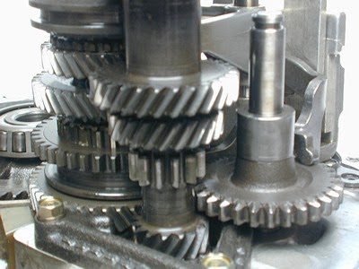
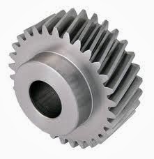
The gears that make up the forward gear ratios are all helical gears. The teeth on helical gears are cut at an angle to the face of the gear. When two teeth on a helical gear system engage, the contact starts at one end of the tooth and gradually spreads as the gears rotate, until the two teeth are in full engagement. This gradual engagement makes helical gears operate much more smoothly and quietly than spur gears. Also, because of the angle of the gear teeth, more teeth are in engagement at any one time. This spreads the load out more and reduces stresses.
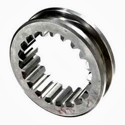
The only problem with helical gears is that it is hard to slide them in and out of engagement with each other. On a manual transmission the forward gears stay engaged with each other at all times, and collars that are controlled by the shift stick lock different gears to the output shaft (see How Manual Transmissions Work for details). The reverse gear on your manual transmission uses an idler gear (the large spur gear visible at the right side of the picture below), which has to slide into mesh with two other spur gears at the same time in order to reverse the direction of rotation.
Spur gears, which have straight teeth, slide into engagement much more easily than helical gears, so the three gears used for reverse are spur gears>
Each time a gear tooth engages on a spur gear, the teeth collide instead of gently sliding into contact as they do on helical gears. This impact makes a lot of noise and also increases the stresses on the gear teeth. When you hear a loud, whirring noise from your car in reverse, what you are hearing is the sound of the spur gear teeth clacking against one another!
HOW THE POWER(rack and pinion) STEERING WORKS?
The components of the power steering consist of:
• Power steering pump
•Power steering fluid
•Speed sensor
•Steering rack
•Steering wheel
The POWER STEERING PUMP It is a rotary pump driven by a belt from the main pulley of the engine at roughly twice engine speed. This pump is designed to circulate POWER STEERING FLUID through the SPEED SENSOR and at very high pressure from the pump to the STEERING RACK. STEERING WHEEL movements cause pressurized fluid to be directed one way or the other inside the steering rack.
The steering rack is under the vehicle between the front wheels. The power steering fluid is directed under pressure to the rack. The steering wheel provides input from the driver to the rack, directing power assist when necessary.
Power steering fluid is designed to withstand about 1200 lbs of pressure without breaking down or foaming. Hondas use a special fluid that is a type of whale oil. Do not attempt to use any other type of fluid, as it will foam under pressure and destroy the seals in the rack assembly causing loss of fluid resulting in loss of power assisted steering.
The speed sensor is attached to the transmission and senses vehicle speed. The power steering system is designed to provide maximum assist when the vehicle is traveling slowly. As speed increases, assist pressure decreases. So that at 35 MPH the power steering is providing no assist. The power resumes with reduction of speed.
On vehicles with four wheel steering, the front rack assembly provides power assist to the rear wheels.
A new type of power steering is now available on the Civic hybrid. This steering is based on electricity, not fluid. This means that the power steering is available, even if the engine is not running, such as when the auto off feature is in effect. The electrical power steering has several benefits: Less power from the engine to operate, more precise steering, power steering is available at all times, not to mention less weight.
...and that's the way the power steering works!! :)
Tuesday 29 January 2013
Precision Gears
Majority of this types of gears are used where quality matters the most along with durability.
The gear tooth profile of precision gears are grounded after hardening to gain maximum contact with the mating gear and avoid backlash to the maximum.
This ground gears are adaptable to very high RPM with minimum niose.The load carying capacity of precision gears is also remarkable.
These gears are used by Cement Plants, Sugar Mills, Sponge Iron Plants, Fertilizer Plants, Thermal Power Station, Mineral Plants, Chemical Plants, Paper Mills, Mining Industry, Steel Rolling Plants, Textile Plants, Material Handing Equipments, Machine Tools etc.
Industrial Gears
Mechanical Gears
People often looked for constant technological advancement to gauge the progression of a piece of equipment. One noteworthy evolution in the last 50 years is of mechanical drive. Trenchers used to put stuffs in the ground gradually shifted over the last several years to mechanical drive. Mechanical drives used gearboxes, shafts, pulleys, chains and sprockets to drive the trencher chain. Mechanical gear are used to provide a variable output speed from a constant speed power source or to provide torque increase for a variable speed power source as in an automobile. Mechanical drives are less costly than competing electrical drives and their control is much simpler. The disadvantage of these drives is that they are not durable and cannot be controlled as precisely as electrical drives. They cannot transmit as much power as electrical drives when variable speed is essential. They are used in industries ranging from aerospace to mining and heavy industry. With the advanced technology, the working of mechanical drive has become more efficient. Specific characteristics like low-stress, universal mounting, high-strength monobloc casings, high-energy efficiency and low noise level are designed. The monobloc design has increased center distances between the output shaft bearings, making the unit able to withstand significantly higher radial loading. Mechanical drives have internal spaces that have void spaces where residues can be deposited.
Idler Gears
Idler gear wheel placed between two other gears to transmit motion from one to the other. It does not alter the speed of the output, but it does alter the direction it turns. It is used to ensure that the rotation of two gears is the same. An idler gear is placed between two gears. The idler gear rotates in the opposite direction as the driver gear and the follower gear rotates in the opposite direction of the idler, the same direction of the driver. It is also used to change the spacing between the input and output axes. It does not change the gear ratio between the input and output gears. All the gears and wheels that turn inside the treads of a battle tank are all idler gears that transfer power from the input gear to the output gear to move the tread and move the tank forward. The power take off mechanism includes a gear train with an input idler gear, a first intermediate idler gear, a second intermediate idler gear and an output gear. The input idler gear receives a rotary input and the first intermediate idler gear meshes with the input gear and the second intermediate idler gear. The output gears transmit rotary power to one of the first and second axles.
Worm Gears
Industrial Gears
We service a wide spectrum of industrial gears including mining, pulp and paper, tunnel boring, compressor drives, steel, automotive, aerospace and many more by providing quality gears. We can provide ground gears up to 95" in diameter and cut gears over 20 feet in diameter. Our diverse capabilities include:
External gears to 240 inches diameter.
Internal gears to 270 inches diameter.
Carburized and external and internal ground gears to AGMA Quality 14.
Spur, helical, and double helical gears.
Bevel Gears.
Ground worms and worm gears.
Large machine shop, including extensive CNC capabilities.
Reduction Gears
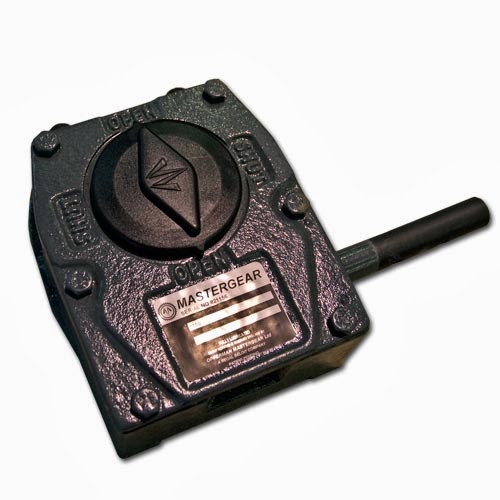
We are manufacturers and exporters of worm reduction gear box. Casings are made from fine graded cast iron. Worm are made from nickel alloy steel, case hardened and precision ground surfaces. Worm Wheels rims made from Aluminium, Bronze and Phosphorous Bronze (PB2C) casted on Graded Cast Iron hubs. The worm gears are hobbed with multi start hobs to ensure a high load carrying capacity. All these internals are supported on high quality Ball / Roller Bearings designed for life under Grease / oil splash lubrication. Hardened and ground worm drives are available.
Spur Gears
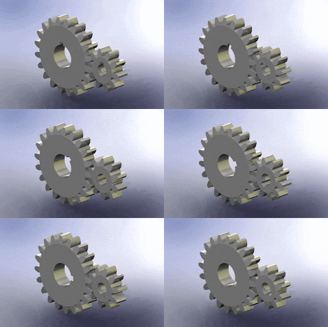
The company manufactures durable and highly efficient spur gears upto 5000 mm OD 50 Module in Cast Iron & Steel (Single, Double & Multi Starts) for Cranes, Material Handling Equipment, For Cement plants, Sugar plants, Chemical plants and Mineral Processing Plants, Coal Handling Equipment, Steel Rolling Mills & Petrochem sectors. They connect parallel shafts, have involute teeth that are parallel to the shaft and can have internal or external teeth. They cause no external thrust between gears. They are inexpensive to manufacture. They give lower but satisfactory performance. They are used when shaft rotates in the same plane. The main features of spur gears are dedendum, addendum, flank and fillet. Dedendum cylinder is a root from where teeth extend, it extends to the tip called the addendum circle. Flank or the face contacts the meshing gear, the most useful feature if the spur gears. The fillet in the root region is kinetically irrelevant.
Planetary Gears
A gearset in which all of the gears are in one plane, grouped around each other like the planets around the sun. The central gear is called the "sun gear". In mesh with it is a circular grouping of gears, called "planet gears", mounted on a rotating carrier. The planet gears also engage teeth on the inner periphery of the "ring gear". By holding any one of the three gear elements motionless, different ratios can be produced between the other two. Planetary gearsets are common in automatic transmissions.
Automotive Gears
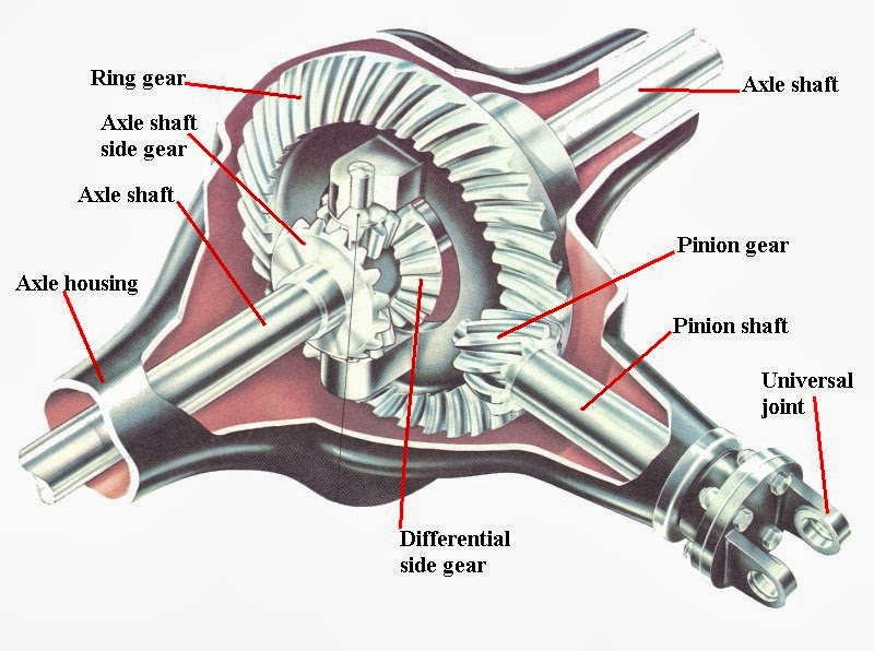
Automotive Gears play an important role in trucks, car, buses, motor bikes and even geared cycles. These gears control speed and include gears like ring and pinion, spiral gear, hypoid gear, hydraulic gears, reduction gearbox. Automotive gear ratio is the number of turns of the drive wheels in relation to the number of turns of the engine. If the engine is considered the input and the drive wheel is considered to be the output then the input gear or the pinion is said to mate with the output gear or the ring gear to drive or rotate it. Depending on the size of the vehicle, the size of the gears also varies. There are low gears covering a shorter distance and are useful when speed is low. There are high gears also with larger number of teeth. These high gears cover a longer distance with one revolution of pedal.
Angular bevel gears: Used in rotor craft drive system to redirect the shaft from horizontal gas turbine engine to the vertical rotor.
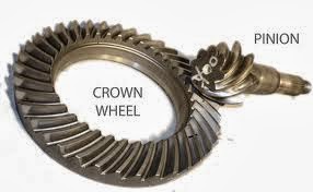
Crown wheel and pinion: Used in motorcycle automotive gearboxes.
Differential gear: Helps two wheels of the car to rotate differentially with respect to each other.
Fine pitch gear: It is an anti-backlash gear used to minimize errors introduced by backlash.
Helical bevel gears: Used as storage and retrieval units in automobiles.
Helical gears: In helical gear the teeth are cut an angel, allowing for more gradual and smoother meshing between gear wheels.
Herringbone gears: Used for power transmission in automobiles.
Internal gears: Used in rollers and as tools for creating solid models of drive systems.
Master gear: Used to determine the accuracy of work gears.
Ring gears and pinion: Used in heavy truck differentials. Also used to convert the driving force from the drive shaft (power unit) to the drive wheels.
Drive Gears :-
Everyone has seen a bicycle or used one and noticed that it is driven by a large driver gear wheel with pedals attached. Smaller gears at the back are driven round, in turn driving round the back wheel. As the back wheel turns the bicycle moves forwards. Gears driven by chains are used in machinery, motorcycles, in car engines and have many more applications. A chain is made up of a series of links with the links held together with steel pins. This arrange makes a chain a strong, long lasting way of transmitting rotary motion from one gear wheel to another.
Bevel Gears :-
Bevel Gears connect intersecting axes and come in several types. The pitch surface of bevel gears is a cone. They are useful when the direction of a shaft's rotation needs to be changed. Using gears of differing numbers of teeth can change the speed of rotation. They are usually mounted on shafts that are 90 degrees apart, but can be designed to work at other angles as well. These gears permit minor adjustment during assembly and allow for some displacement due to deflection under operating loads without concentrating the load on the end of the tooth. For reliable performance, Gears must be pinned to shaft with a dowel or taper pin.
Types:
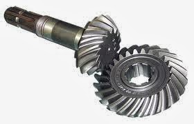
The teeth on bevel gears can be straight tooth , spiral or bevel. In straight tooth bevel gears teeth have no helix angles. They either have equal size gears with 90 degrees shaft angle or a shaft angle other than 90 degrees. Straight bevel angle can also be with one gear flat with a pitch angle of 90 degrees. In straight when each tooth engages it impacts the corresponding tooth and simply curving the gear teeth can solve the problem. Spiral bevel gears have spiral angles, which gives performance improvements. The contact between the teeth starts at one end of the gear and then spreads across the whole tooth. In both the bevel types of gears the shaft must be perpendicular to each other and must be in the same plane. The hypoid bevel gears can engage with the axes in different planes. This is used in many car differentials. The ring gear of the differential and the input pinion gear are both hypoid. They also have sliding action along the teeth, potentially reducing efficiency.
(sprial bevel gear)
Applications:
A good example of bevel gears is seen as the main mechanism for a hand drill. The bevel gears find its application in locomotives, marine applications, automobiles, printing presses, cooling towers, power plants, steel plants, defence and also in railway track inspection machine.
Straight tooth Gears:-
Straight bevel gears are the simplest of the bevel gears. They are manufactured on precision generating machines by indexing method ensuring that the teeth should be of tapered depth and thickness. Teeth are cut on the outside of the cone. They have a straight tooth geometry, which if extends, passes through the intersection of their axes. Straight bevel angle can also be with one gear flat with a pitch angle of 90 degrees. These have conical pith surfaces that operate on intersecting axes. They can be designed and cut to operate on any shaft angle. In straight bevel gears when each tooth engages it impacts the corresponding tooth and simply curving the gear teeth can solve the problem. Straight bevel gears come in two variations depending on the fabrication equipment. They are grouped into gleason type and the standard type. Major percentage of them is of gleas on type with a coniflex form that gives almost an imperceptible convex appearance to the tooth surface. In the standard form, the gear has no profile shifted tooth. These gears are recommended at less speed and when loads are light. At higher speed they make noise. The most preeminent function of these gears is in a bevel gear differential. Straight tooth gears are also used in chemical industries, steel plant, machine tools, cement plant, textile processing, material handling system, sugar mills and cooling towers etc.
Transmission Gear :-
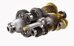
We are the exporters of automotive engine gears like transmission gears, differential gears, propeller shaft components for trucks, tractors, passenger cars, construction machinery and other LCVs.


